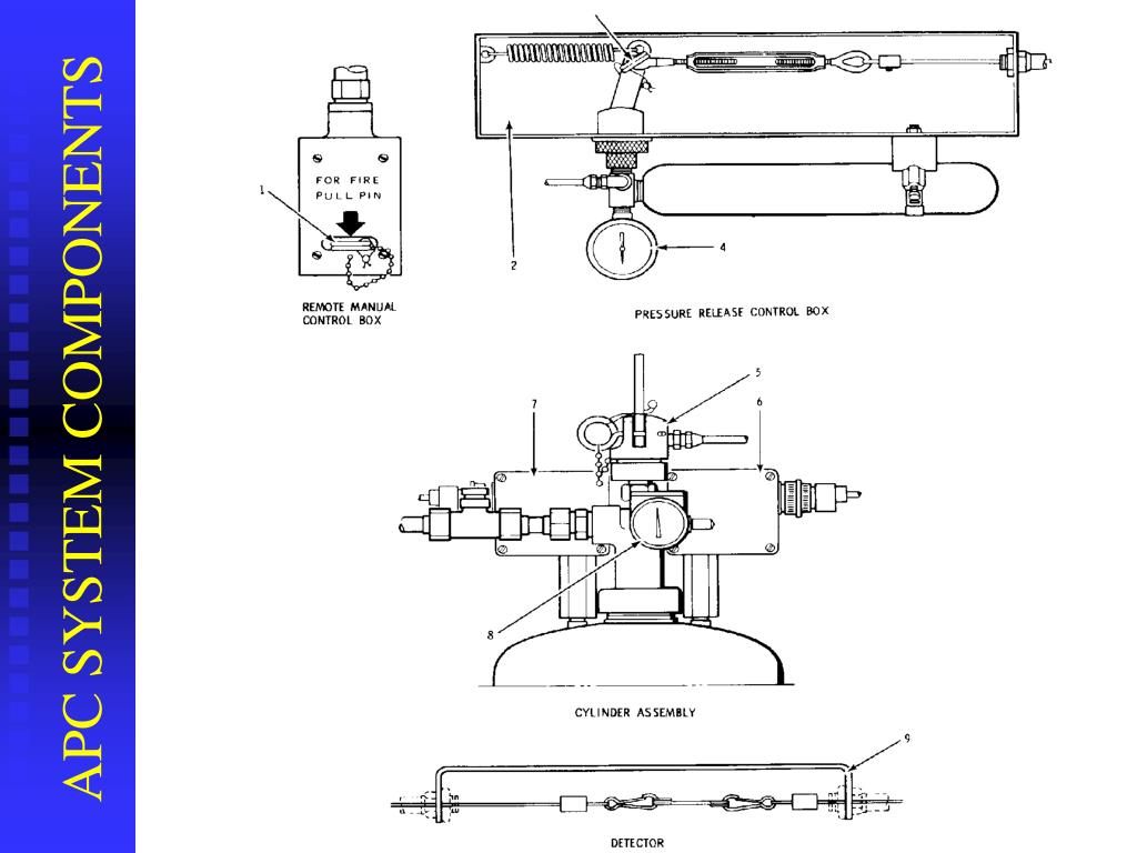
WALL MOUNT FULL BACKGUARD INSTALLATION RECOMMENDED INSTALLATION ORDER: 1) VENT HOOD 2)BACKGUARD SYSTEM 3) RANGE 1. Locate and level range per installation instructions. After unpacking all backguard system parts, locate the Back Section 1/4” (see fig. 03) above and centered over the Island Trim attached to the range. Range Guard systems assure quick fire detection and suppression, 24-hour, continual fire protection, superior wet chemical coverage that quickly suppresses fires and prevents reflash and quick clean up. Range Guard exceeds UL 300 standards and are designed to easily fit in any kitchen layout. Range Guard systems assure quick fire detection and suppression, 24-hour, continual fire protection, superior wet chemical coverage that quickly suppresses fires and prevents reflash and quick clean up. Range Guard exceeds UL 300 standards and are designed to easily fit in any kitchen layout. RANGE ROVER EVOQUE. DISCOVERY SPORT. ALL-NEW DISCOVERY. RANGE ROVER VELAR. ALL-NEW RANGE ROVER.
Краткое содержание страницы № 1
Installation Manual
PATENT PENDING
Energy Star SteamChef Models 22CET3.1 and 22CET6.1
th
1333 East 179 Street
Cleveland, Ohio 44110
Phone: (216) 481 - 4900
1-800-338-2204
Fax: (216) 481 - 3782
www.clevelandrange.com
Part No. 22CET(ES)-INM REV. C 5/07

Краткое содержание страницы № 2
FOR YOUR SAFETY Do not store or use gasoline or other flammable vapors or Improper installation, adjustment, alteration, liquids in the vicinity of this service, or maintenance can cause property or any other appliance. damage, injury, or death. Read the installation, operating and maintenance instructions thoroughly before installing or servicing this equipment. ELECTRIC SHOCK HAZARD DEATH, INJURY, or EQUIPMENT DAMAGE can result from touching any component inside this appliance when
Краткое содержание страницы № 3
Range Guard Installation Manual Pdf
Cleveland STATEMENT OF POLICIES L I M I T E D W A R R A N T Y CLEVELAND RANGE products are warranted to the original purchaser to be free from defects in materials and workmanship under normal use and service for the standard warranty period of one year from date of installation or 18 months from date of shipment, which ever comes first. CLEVELAND RANGE agrees to repair or replace, at its option, f.o.b. factory, any part which proves to be defective due to defects in material or workmansh
Краткое содержание страницы № 4
Краткое содержание страницы № 5
INSTALLATION MANUAL SteamChef 22CET3.1 and 22CET6.1 Table of Contents Chapter.....................................................................................................................Page 1 Product Information................................................................................................... 1 A. Product Information............................................................................................................................ 1 B. Product Informatio
Краткое содержание страницы № 6

CHAPTER 1 PRODUCT INFORMATION A. Product Information • This manual covers the installation of 22CET3.1 and 22CET6.1 SteamChef Steam Cookers (steamers), and their standard features and options. • Other than selection of options, there are presently no significant design, parts, or operating differences among appliances with this model number. • Figures 2-1 and 2-2 illustrate the dimensions, clearances, and major external features of 22CET’s. B. Product Information Plate The Product Infor
Краткое содержание страницы № 7
CHAPTER 2 GENERAL INFORMATION A. Laws, Codes, and Regulations This equipment should be installed only by qualified, professional plumbers, pipe fitters, and electricians. 1. The installation of this appliance must conform with: a. The National Electrical Code, ANSI/NFPA 70 (latest edition), or the Canadian Electrical Code, CSA C22.2, or local codes, as applicable. • When installed, the appliance must be electrically grounded in accordance with the above. • NOTE: This appliance is not GF
Краткое содержание страницы № 8
C. Product Views 32.162 21.625 30.177 21.625 18.359 22.395 22.395 C1 C2 28.000 30.177 3.000 12.000 90° 24.000 Figure 2-1 SteamChef 3.1 Dimensions and Clearances 3

Краткое содержание страницы № 9
32.162 21.625 30.177 26.913 26.750 30.949 30.750 C1 C2 4.000 2 28 8..0 00 00 0 29.331 30.177 120° 12.000 90° 24.000 Figure 2-2 SteamChef 6.1 Dimensions and Clearances 4
Краткое содержание страницы № 10
CHAPTER 3 INSTALLATION Operating this appliance out of level can cause DEATH, INJURY, and EQUIPMENT DAMAGE. This appliance must be level both front-to-back and side-to-side in all installations. NEVER operate this appliance out of level. If this appliance is suspected to be out of level, shut it down at once and call your qualified Cleveland Range authorized service agency immediately. A. Select a Location 1. For safe and efficient operation: a. Installation must comply with all local fir
Краткое содержание страницы № 11
B. Installation of a SteamChef 22CET3.1 or 22CET6.1 DANGER Improper installation, adjustment, alteration, service or maintenance can cause DEATH, INJURY, AND EQUIPMENT DAMAGE Read and understand the installation, operation and maintenance instructions before installing, using, or servicing this equipment. DO NOT INSTALL a SteamChef steamer if it is damaged or if damage is suspected. Install the SteamChef steamer according to the policies and procedures outlined in this manual. DANGER
Краткое содержание страницы № 12
C. Install the Legs 1. The legs must be used unless the 22CET is installed on a Cleveland Range stand. 2. In order to safely assemble the legs onto the 22CET without damage, follow this procedure: a. Check that the feet are fully retracted into the legs. Do not tighten. The feet should easily screw in and out using fingers only. b. Remove the four foam packing blocks from the upper packing assembly, and position them on a flat surface (e.g. the floor) as shown in Figure 3-1. c. Center the

Краткое содержание страницы № 13
Drain Legs FIT UP OF KLEANSHIELD PIPE Figure 3-4 KleanShield Figure 3-3 KleanShield Installation (SteamChef 3.1 shown) F. Install the Fan Guard and Air Diverter • See Figure 3-5 1. Hold the fan guard so that the large ends of the keyhole slots are towards the bottom of the steamer. 2. Place all four large end openings of the keyholes over the mounts located on the rear wall of the steamer. 3. Pull it down so that the narrow ends of the slots are pulled tight over the mount
Краткое содержание страницы № 14
H. Install the Rear Vent • For 22CET’s not on stacking stands: 1. Using pipe thread sealant (not provided), install the provided brass street ell into the bulkhead fitting on the rear of the 22CET. See Figure 3-7. 2. Connect the drain to a free air vented drain line. See Figure 3-8. VENT DRAIN Figure 3-7 Steam Vent (SteamChef 3.1 Shown) I. Connect the Free Air Vented Drain Line DEATH, INJURY, EQUIPMENT and PROPERTY DAMAGE will result from improper installation of drain outlet lines
Краткое содержание страницы № 15
8. Do NOT connect this appliance’s drain directly to drains or to the plumbing of any other equipment. (Except when using a Cleveland Range Stacking Stand.) 9. Do NOT install a trap or shutoff in the drain line. 10. Drainpipe Size and Length Guidelines: • Do NOT make a drainpipe outlet extension more than 12 feet long. • Do NOT use more than three elbows. • Up to 6’ pipe: 1 1/2-inch pipe and fittings are acceptable. • Up to 2 elbows: 1 1/2-inch pipe and fittings are acceptable. • 6’ to 12
Краткое содержание страницы № 16
J. Water Supply Requirements and Installation 1. Water Supply Requirements a. Water Quality Unlike most steam cooking equipment, water quality can vary without major loss of performance of a SteamChef steamer. Even hard water will not affect the operation of a SteamChef Steamer as long as it is cleaned with vinegar daily. • See the Operator’s Manual for cleaning instructions. b. Water Supply System • A potable water supply system must be available providing a minimum dynamic pressure of
Badger Range Guard Installation Manual
Краткое содержание страницы № 17
water to supply the reservoir. To use a separate conditioned water supply, use the layout shown in Figure 3-11. i. The steamer has two 3/4-inch GHT fittings, one for the water reservoir and one for the condenser. See Figures 2-1 and 2-2. A Filter Washer (dirt filter) is supplied installed in each of the water inlets. See Figure 3-9. 1. Construct all supply lines up to the 3/4-inch NHT fittings. 2. Flush the water supply lines before connecting them to the 3/4-inch fittings. Figure 3-9 Fi
Краткое содержание страницы № 18
K. Electric Power Supply • The electric supply must match all electrical and wiring requirements specified on the rating plate. • NOTE: This appliance is NOT Ground Fault Interrupter (GFI or GFCI) compatible. • The Electrical Diagram is located on the back of the control-side cover. This appliance is not GFI (GFCI) compatible. Do not use a GFI (GFCI) circuit. Using a GFI (GFCI) circuit can result in injury, equipment damage, and property damage. The connection must be made as follows: 1.
Badger Range Guard Installation Manual
Краткое содержание страницы № 19
L. Electric Power Supply TASK REFERENCE COMPLETED Preparation Page No. Make sure electric power requirements are met 1, 13 Check operating location clearances 3 Make sure location and exhaust hood requirements are met 5 Check field assembly of the 22CET 5 Check field assembly of stand (if used) 6, Separate Instructions Installation Make sure 22CET is level 7 Check drain line connection 9 Check water supply connection 11 Leak tes
Range Guard Installation Manual Pdf
Краткое содержание страницы № 20
Range Guard Installation Manual Pdf
CHAPTER 4. OPERATING TESTS Operating Tests and Final Checkout Procedure • This procedure must be performed by a qualified Cleveland Range authorized service representative. • Complete the Startup Procedure before starting the actual operating tests. • Read and understand all steps of this procedure before starting. • This procedure evaluates the function of the major operating controls of a SteamChef. • This procedure is for SteamChefs equipped with a Keypad Control Panel, Dial Timer Contro